| Been spending some time on calibrating the whole system. |
 |
 |
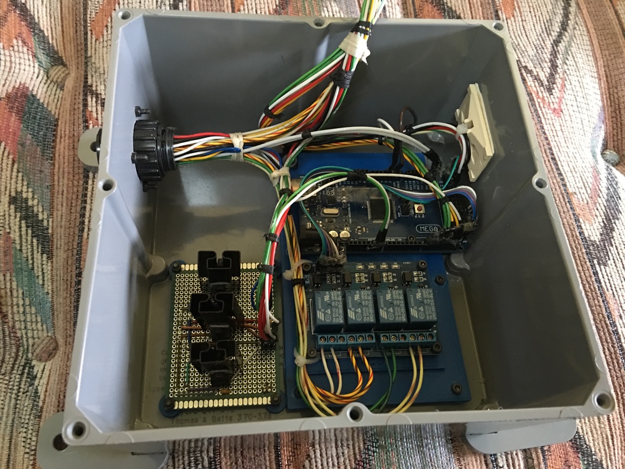
| This is the brains of the ship. This unit will control all pumps and show engine instruments, and fuel tank levels.
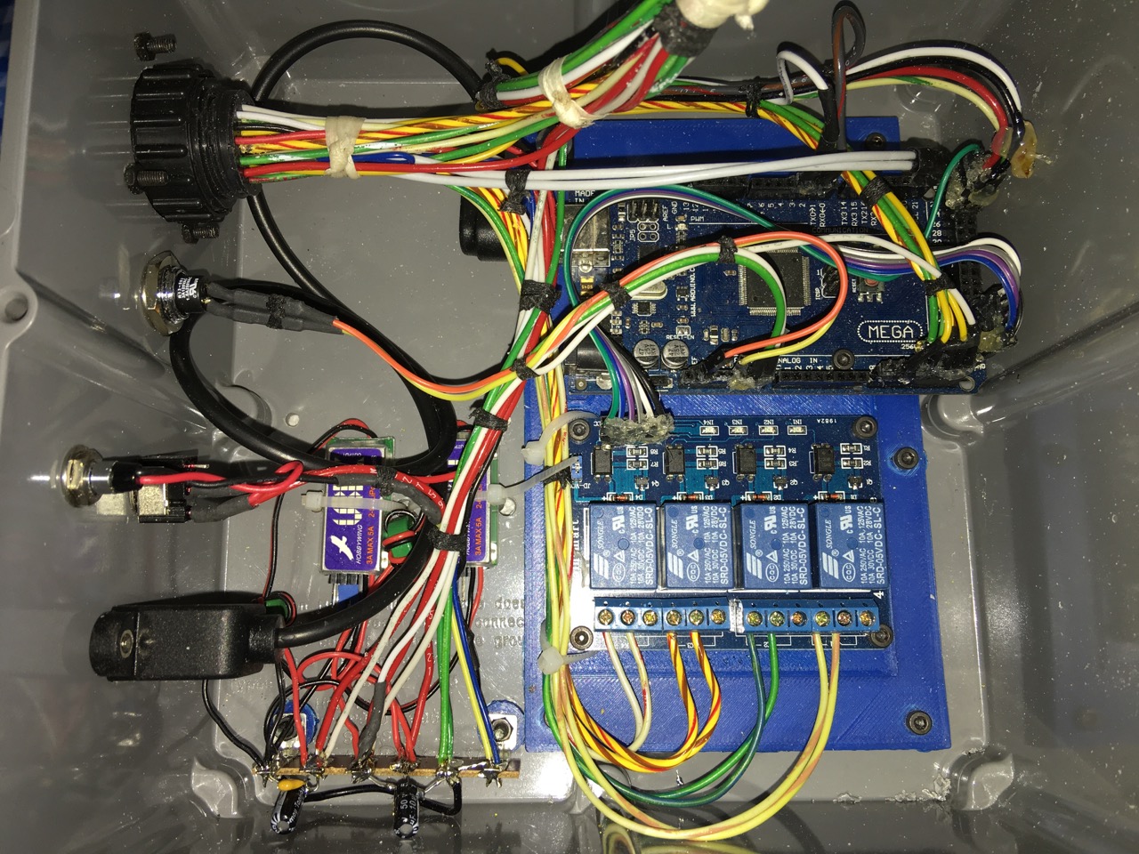
Lower left side are the 3 power regulators, one for 5vdc, 6 vdc, 9 vdc. Lower right side is the relay panel which will control the Fresh Water Pump and Grey Water Pump. Upper left is the Arduino Mega. Not shown here is the input padding module, picture follows. All wires coming into the unit go through this unit which contains opto isolators and op amps to protect the Arduino from damage. |
I could not get steady readings on the fuel tank sensors even though the DC voltage was steady. Put the oscilloscope on the 5 and 6 volt power lines and I discovered a parasitic oscillation was occurring from my power supply. So I scrapped it and came up with these 2 little power supplies instead, shielded and filtered.
I also added an on/off switch with LED, a reset button and a USB panel mount so I can program the Arduino from outside the box.
Live and learn.. |
| |
|
 |
 |
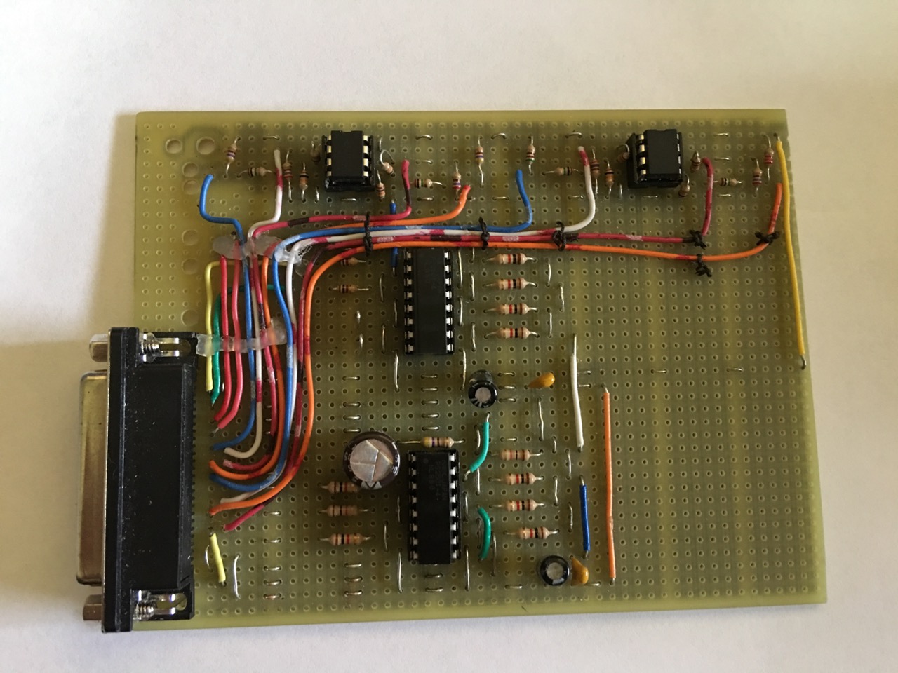
| This is the input padding unit. The 2 16 pin IC's are the opto-isolators. The top 2 8 pin IC's are the op-amps.
Op-amps are used to take sensor values that produce 0 to 2.4 volts and convert it to 0 to 5 volts so the Arduino can sense the full range for accuracy.
The board gets conformal coated and then placed into a grounded metal case and it should all fit into the grey box. |
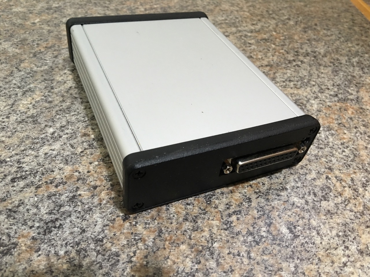
All put together in its metal case. |
| |
|
 |
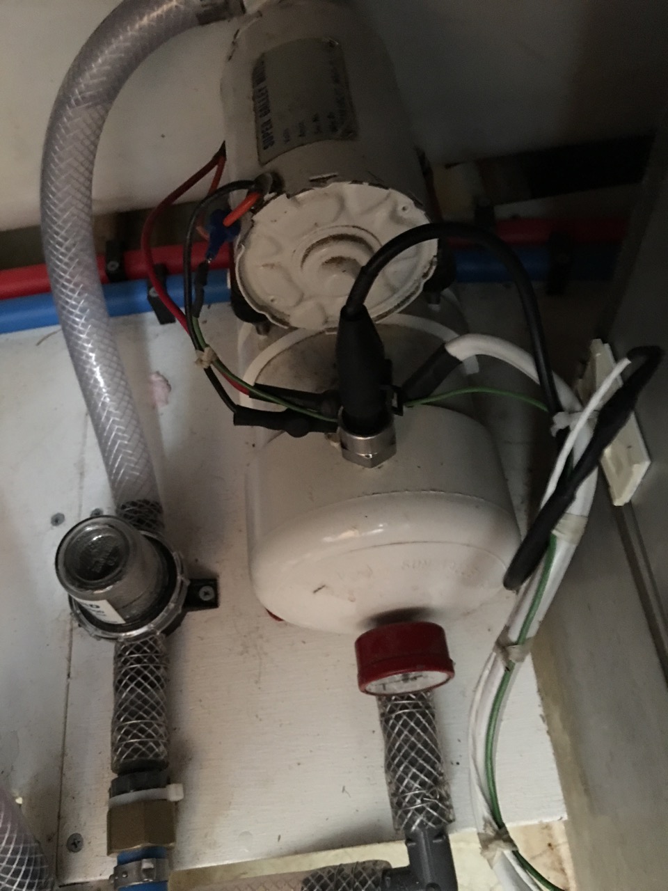 |
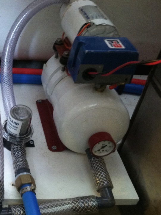
| Now for the fresh water pump dilemma. This pump motor and tank was designed to go to a max of 22 psi and a minimum of 15 psi. So that amounts to a 7 psi differential. The mechanical nightmare you see here has a 10 to 30 psi differential so it would never work. Some idiot somewhere along the line put in the wrong pressure switch. |
Solution was to install a 30 psi pressure transducer which supplies a 0 to 5vdc signal in direct relationship to the pressure. Perfect for use with the Arduino. As shown above a much cleaner installation and no more screwing around with adjustment screws and springs...
Now I can simply program the Arduino to turn on and off at any pressure setting. |
| |
|
 |
 |
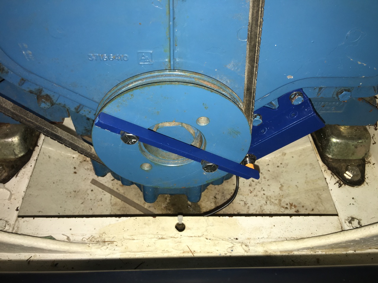
| Next was the RPM sensor. I had to install this bar across the harmonic balancer with a tab running out past the end. All the items in dark blue is what I fabricated and installed. |
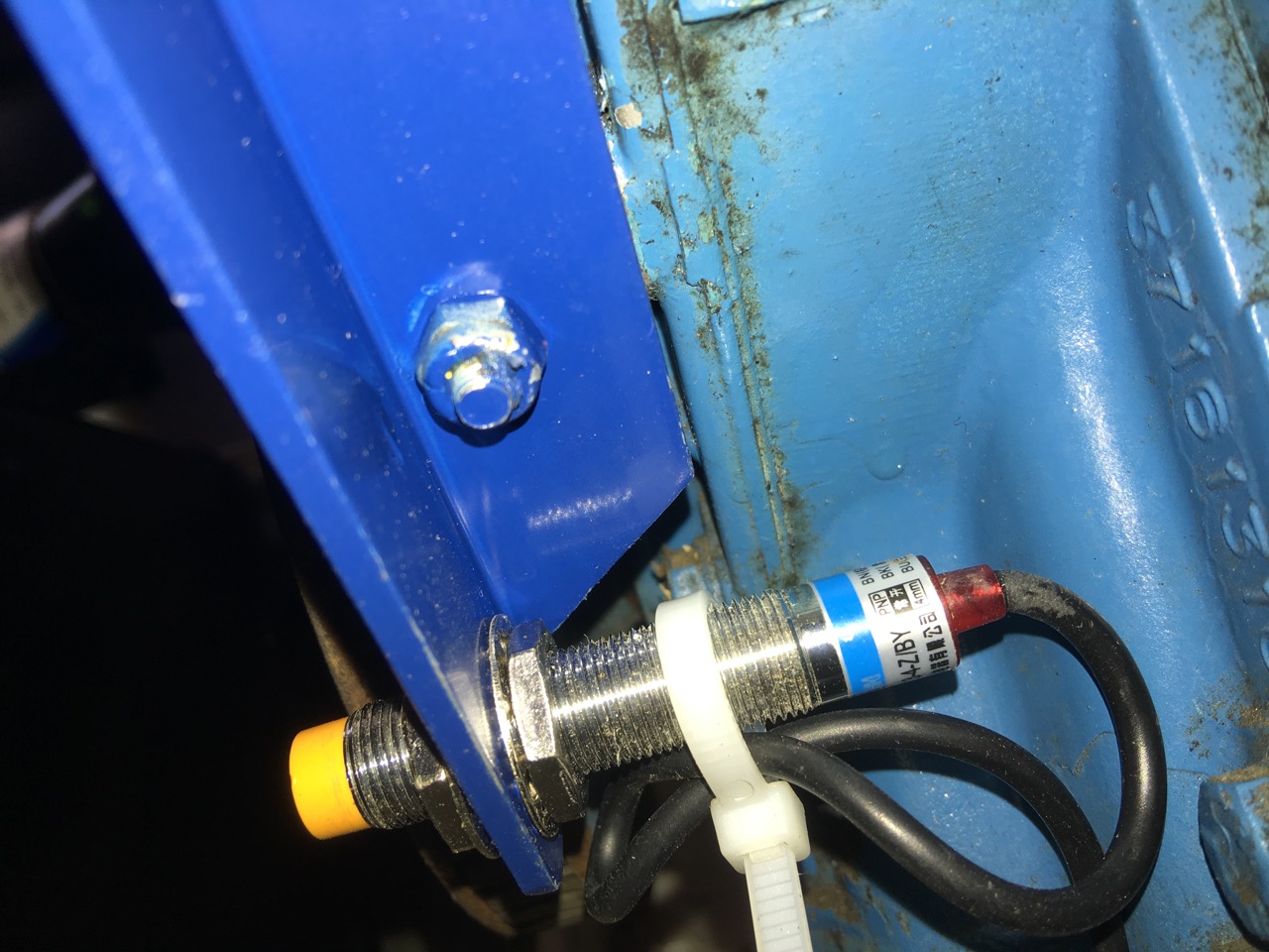
Here is a rear view of the probe and mount. It has a 4mm probe sensitivity, so the adjustment has been set to 2mm from the tab. It is a proximately probe that sends out a pulse each time the tab passes it. It also has a red LED on the back which flashes when activated. |
| |
|
 |
|
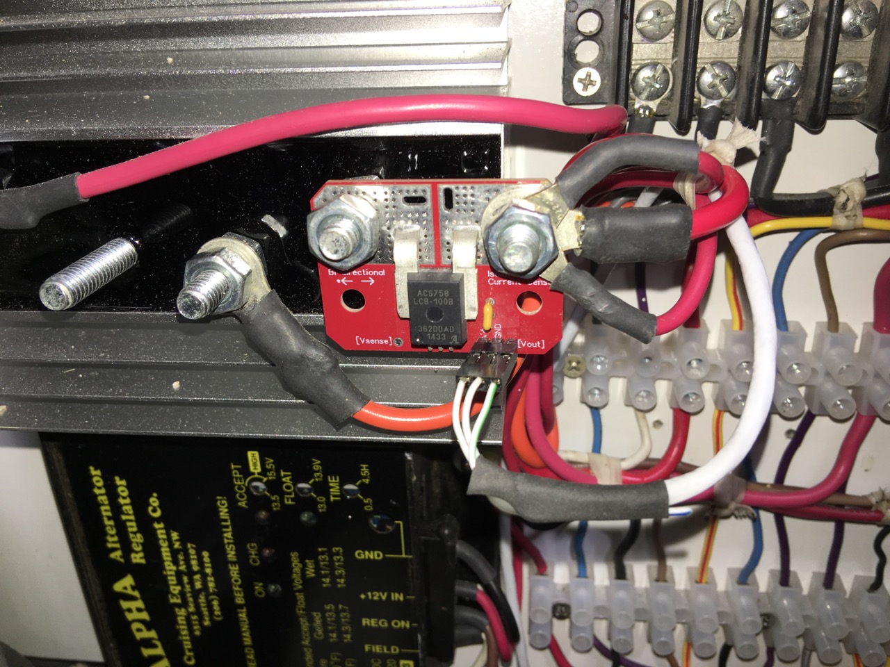
| This is the amp gauge module. It senses 0 to 100 amp and sends a signal to the Arduino. This will measure the charging amps from the engine alternator to the batteries. |
|
| |
|