| Instrument Panel |
 |
 |
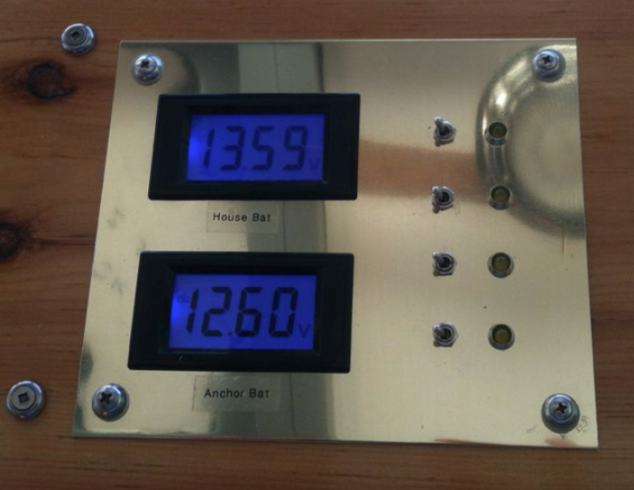
| To the left are the 2 volt meters to monitor house battery and anchor battery states. The windshield wiper switches are on the right. |
To the center is the engine instruments. Yep I know, "where the hell are they?" Well all information is going to be showing on the little blue screen you see here, all run by a micro processor called an Arduino. |
| |
|
 |
 |
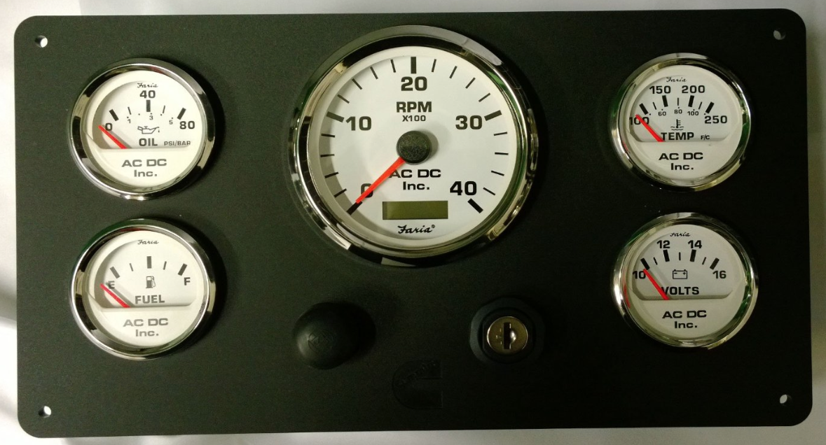
| This is the normal instrument panel that sells for about $500.00. We call these stream gauges nowadays. My little blue panel will replace all this, plus I can simply add another blue panel for the outside steering station. |
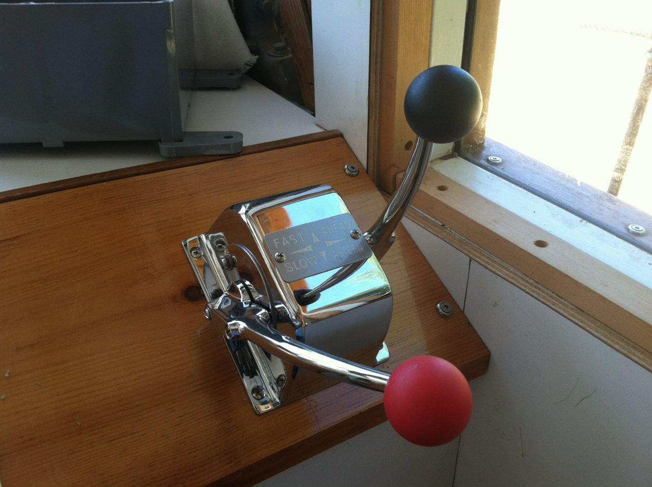
On the right side are the Morse controls installed and connected to the engine. |
| |
|
 |
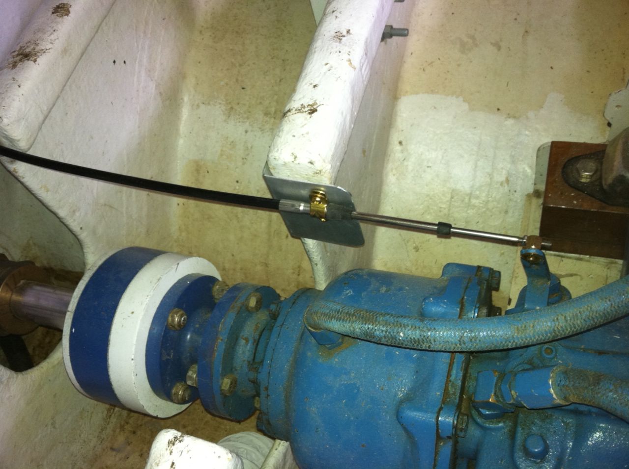 |
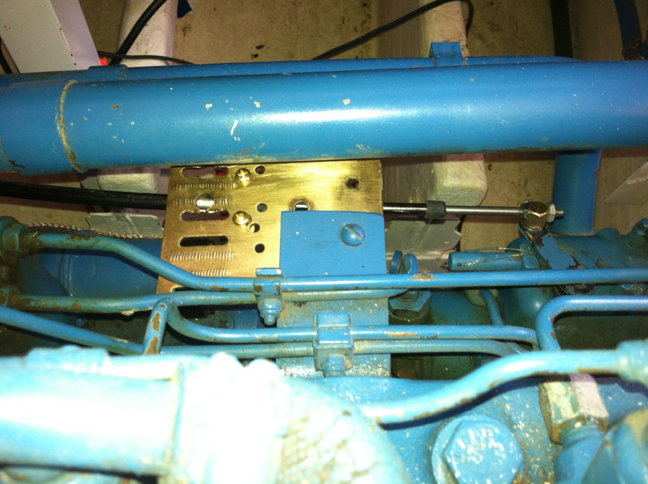
| You can see the other end of the control rod hooked to the throttle on the injector pump. |
Here is the transmission control rod. Had to fabricate the cable bracket. The indents for each position F-N-R had to exactly match the indents on the Morse control. |
| |
|
 |
|
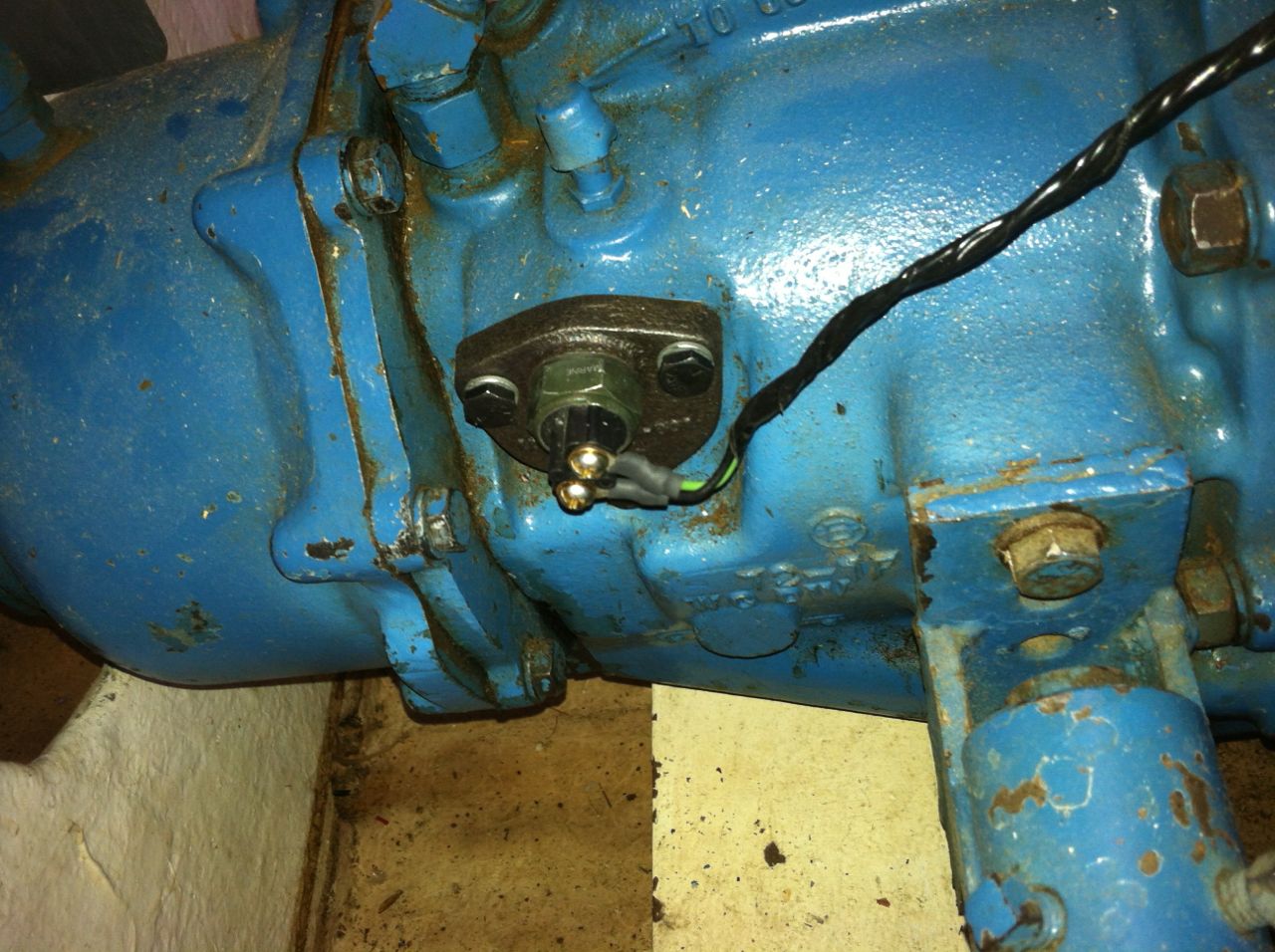
| This little $80 gem is the neutral start switch. I had to add this so no one can start the engine unless it is in neutral. |
|
| |
|
| Exhaust System |
| The exhaust system for this engine is a "Wet Exhaust" system. Where as ocean water is pumped through intercoolers to cool the engine, then it is sprayed into the exhaust gases as they leave the engine at the exhaust manifold. Because the engine is below the water line special units have to be installed to lift the water out of the boat. |
| |
|
 |
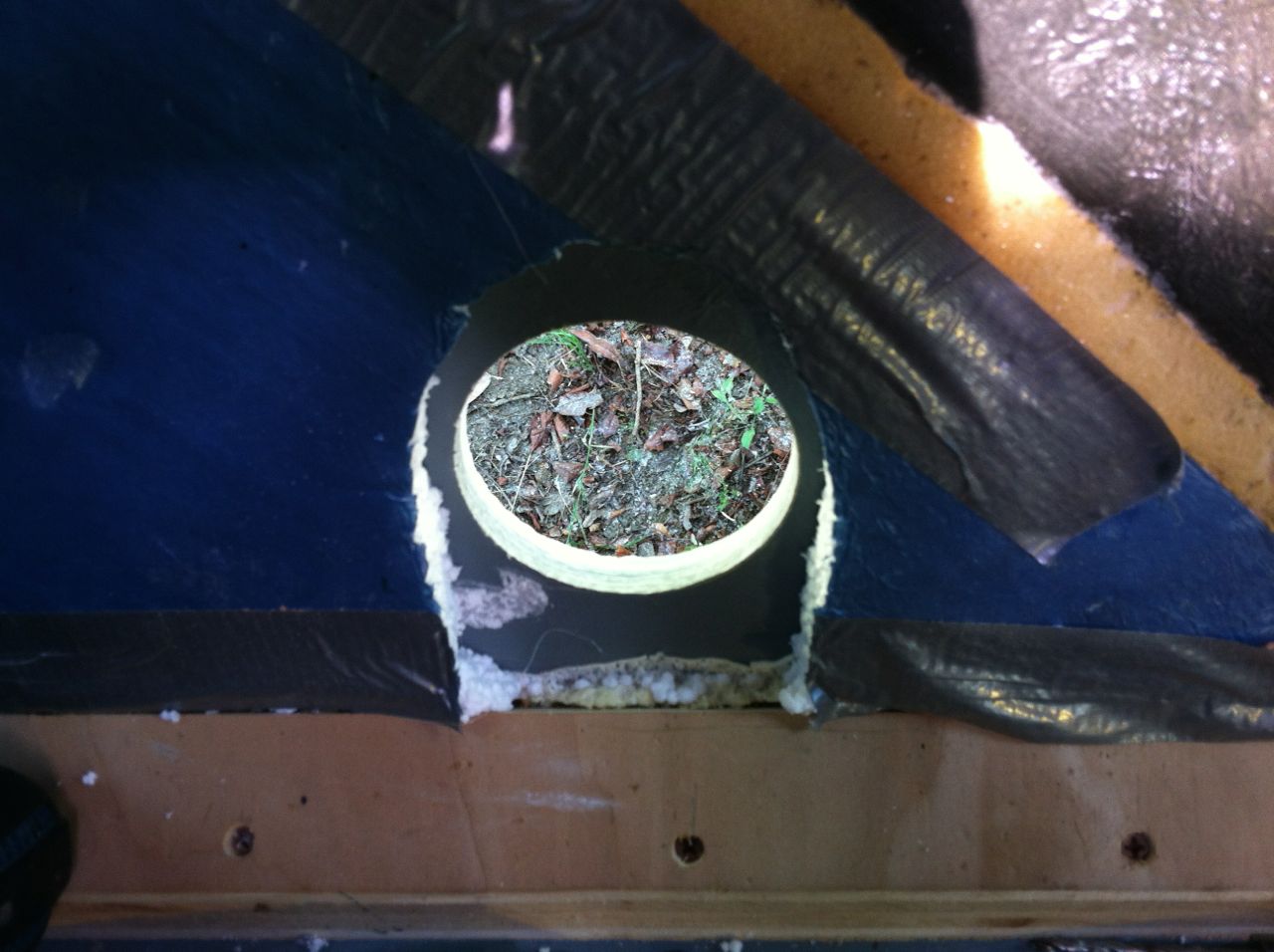 |
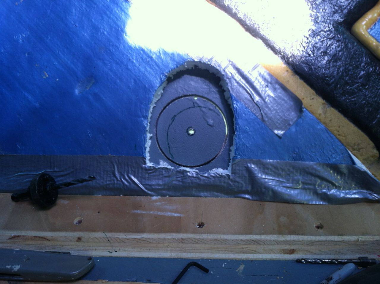
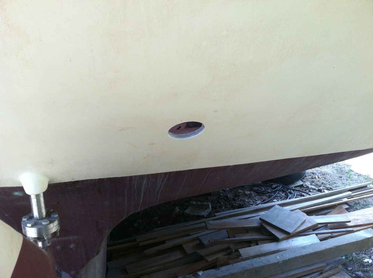
| The exhaust will exit out the back of the ship as close as possible to the center. Here I am nervously figuring out where exhaust port will go.. |
Yikes it's cut out. No going back now !! |
| |
|
 |
 |
| The back view. Just enough above the water line. |
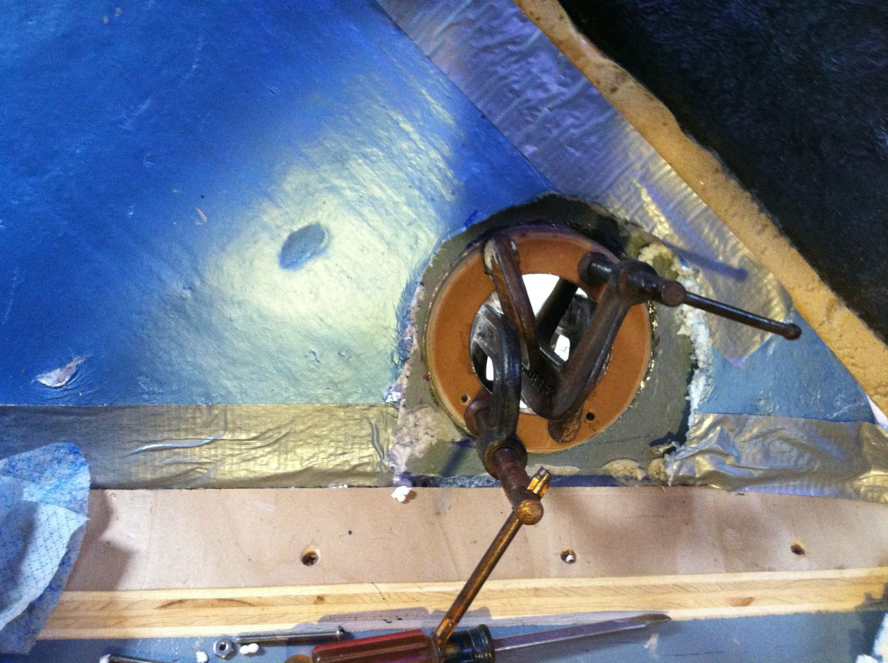
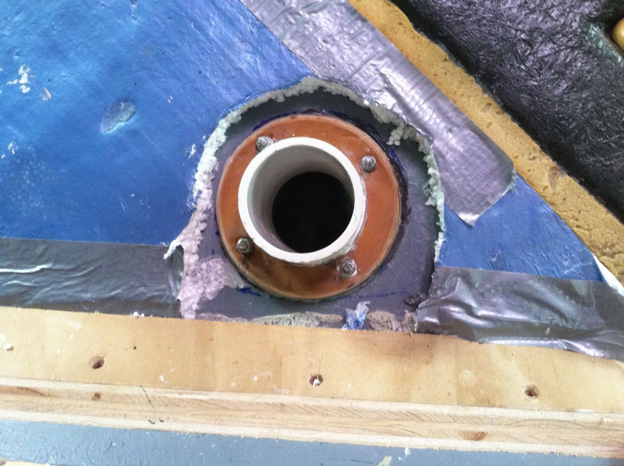
Made backing plate out of MDO 1/2" plywood and glued it in with West System Epoxy. |
| |
|
 |
|
| All done.. Sealed with 5200.. |
|
| |
|
 |
 |
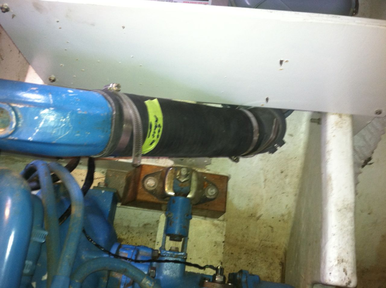
| This is the top view of the engine looking down at the exhaust pipe. First the exhaust goes through an aqua lift which is used to allow the exhaust gases to lift the water up into the 3" hose. It's connected to the back of the aqua lift. (Yes special hose at $21.00 per foot many times it's sold by the inch !) |
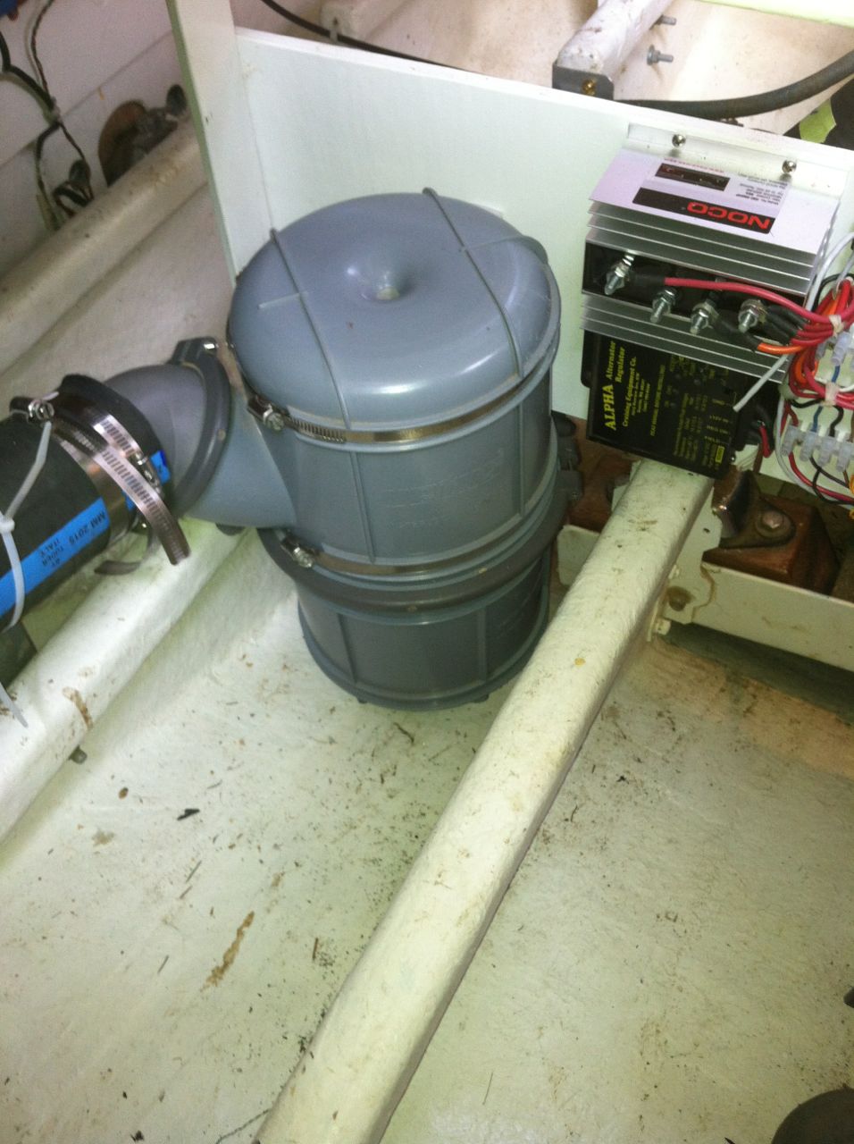
Full view of Aqua-Lift. The exhaust gases lift the water up into the hose you see leaving on the left side. |
| |
|
 |
 |
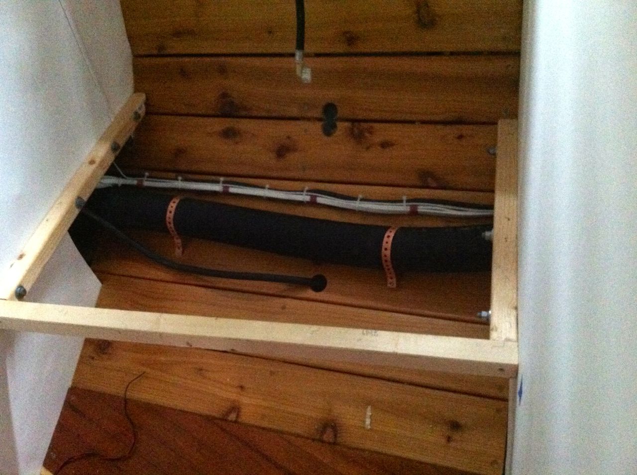
| Then it snakes through the bulkhead and under the support for the washer dryer. Notice I also have the wiring going under it, and I have the water hose inserted through the wall. From there it goes through the side of the closet up to the goose neck. |
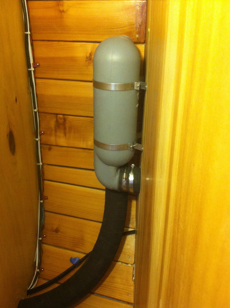
The goose neck allows the water to be lifted way above the water line and then gravity takes over allows it to run out of the back of the boat. You can't see it from this angle but the inlet is on the back. the hose continues on through the closet to the muffler. |
| |
|
 |
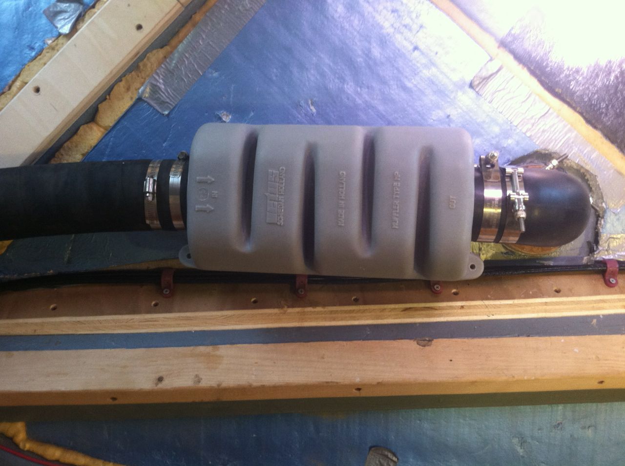 |
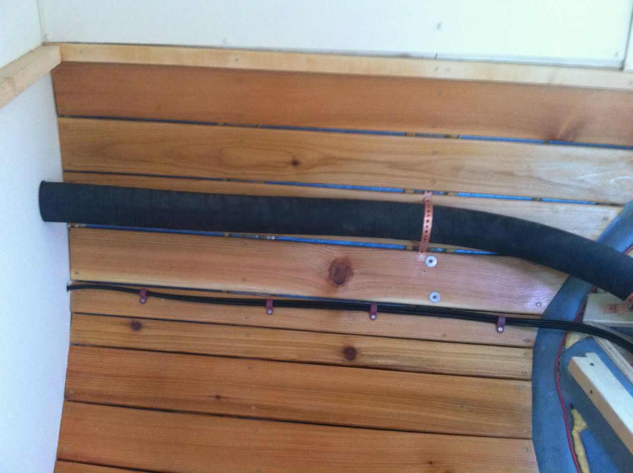
| It runs across the side of the ship and connects to the muffler. The hydraulic steering lines are below it. |
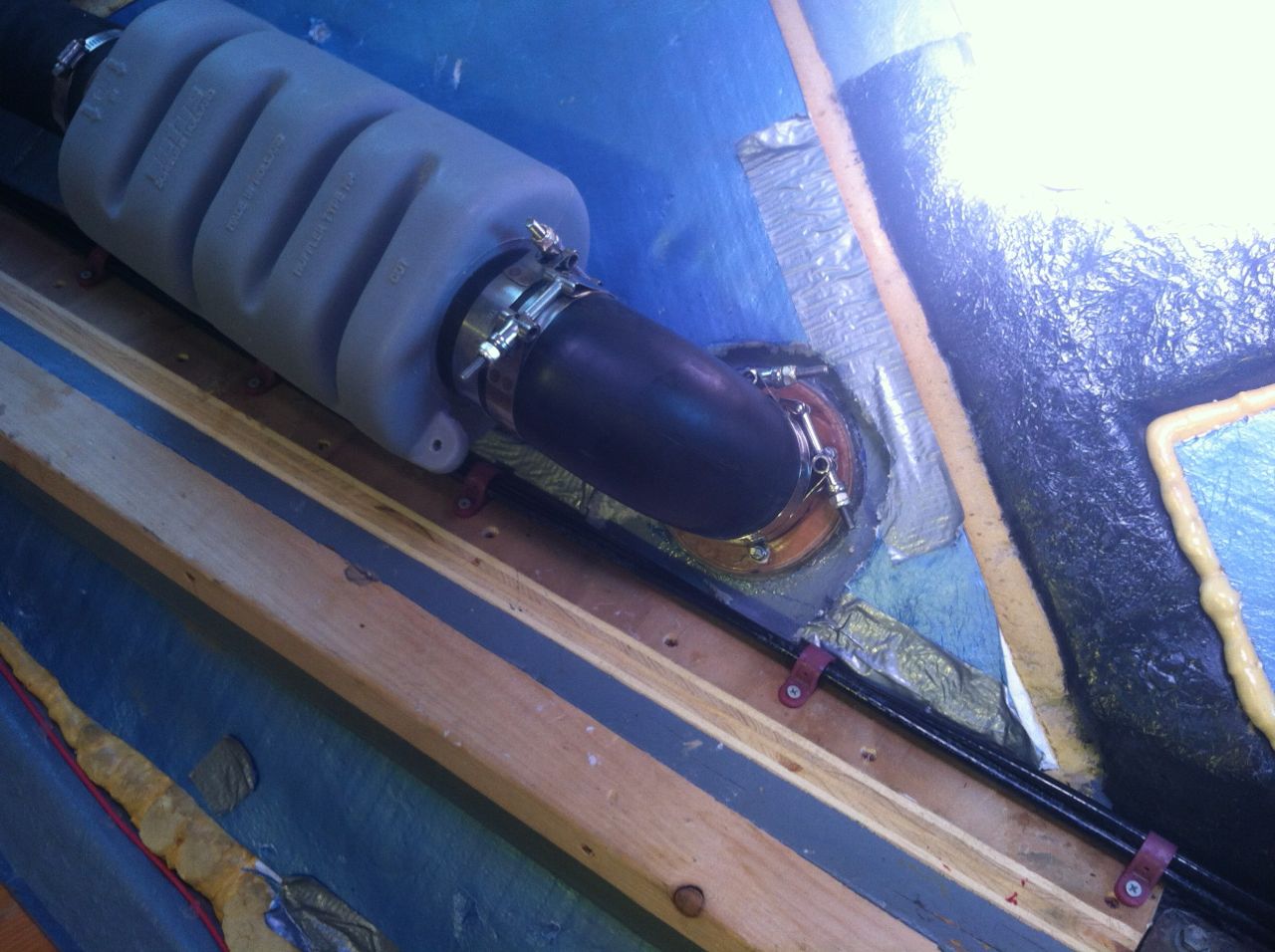
From the muffler it goes at a right angle elbow out the exhaust port we did earlier. |
| |
|
 |
|
| Here's a close up of the elbow connection. Exhaust system done!! |
|
| |
|
Salt (RAW) Water Cooling Inlet |
| |
|
 |
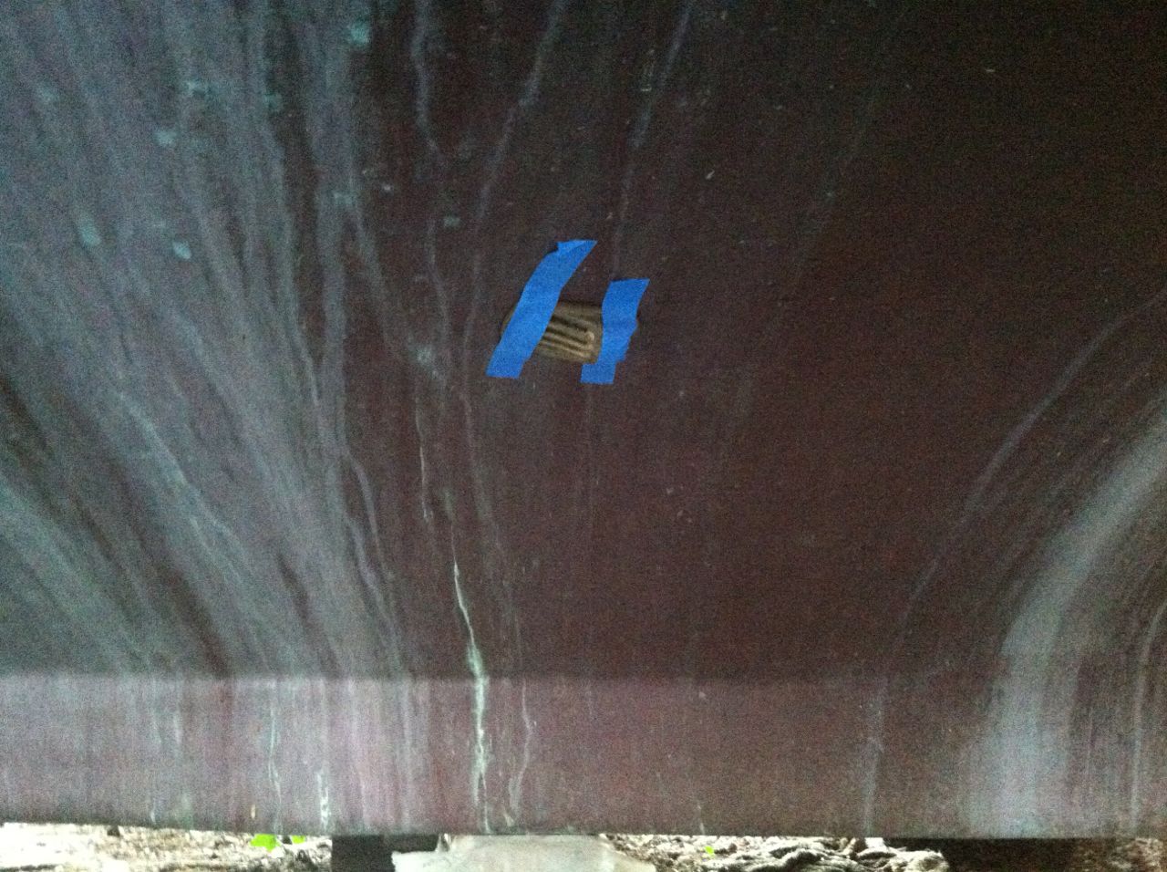 |
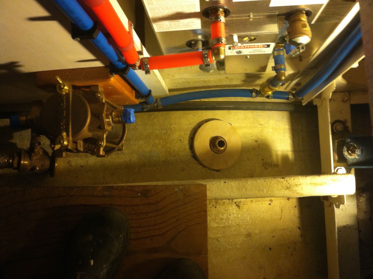
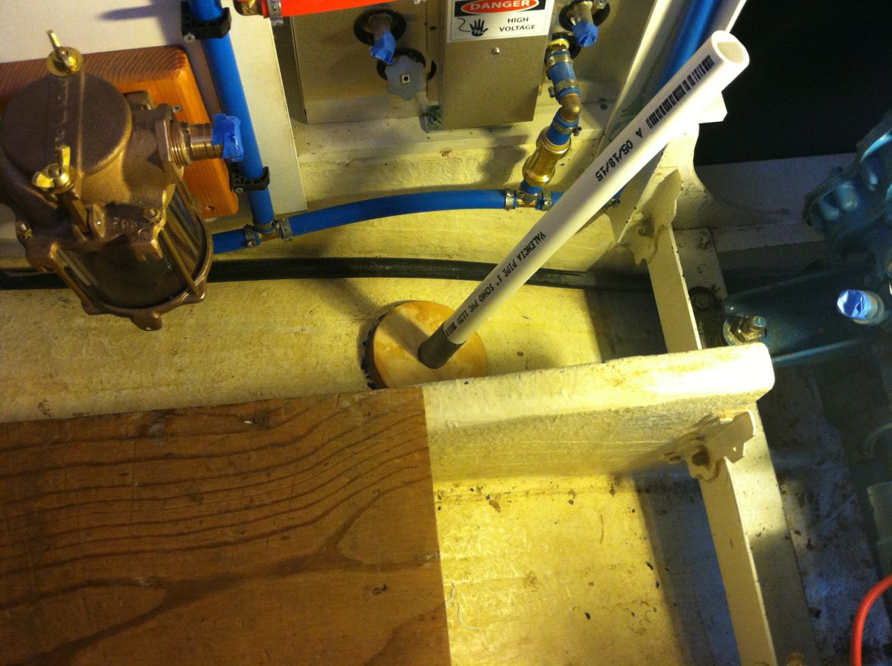
| This shows the thru hull cut out and the plywood backing plate roughed in. The salt water comes in here, goes into the strainer on the left, then into the engine cooling pump. |
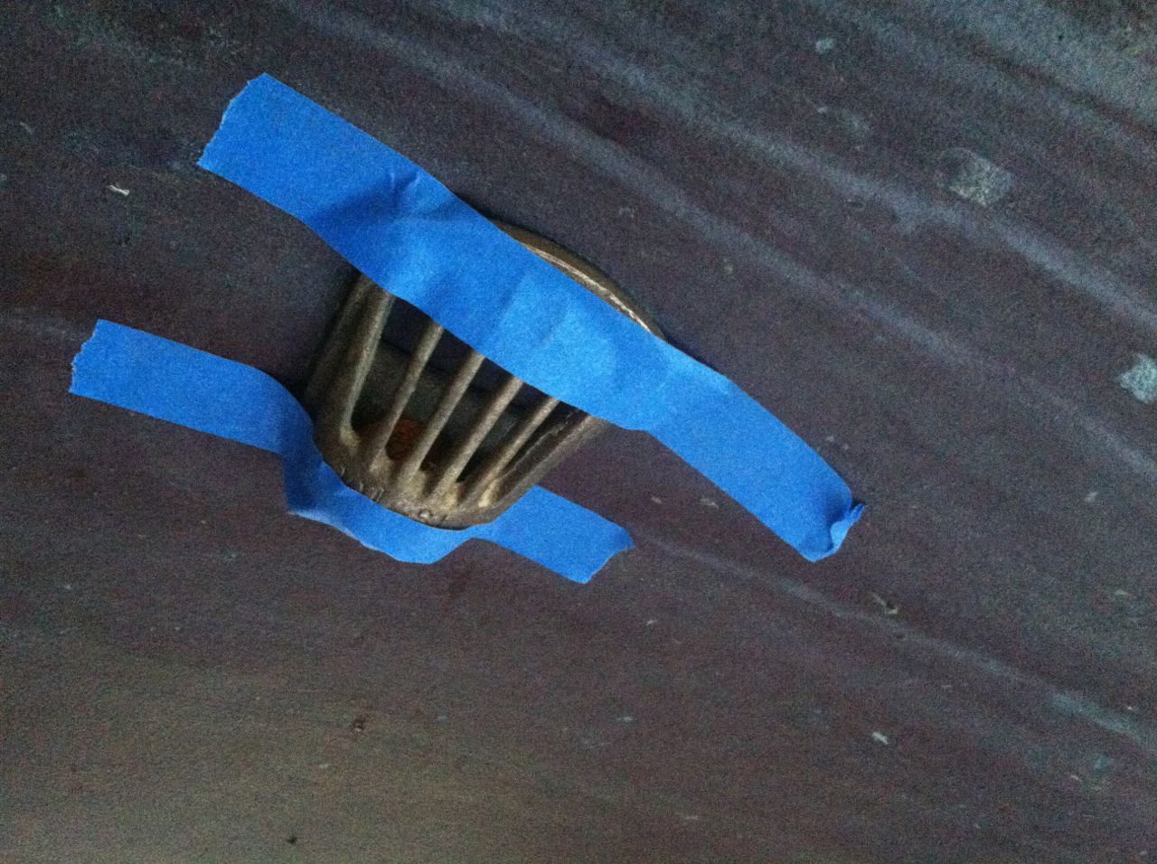
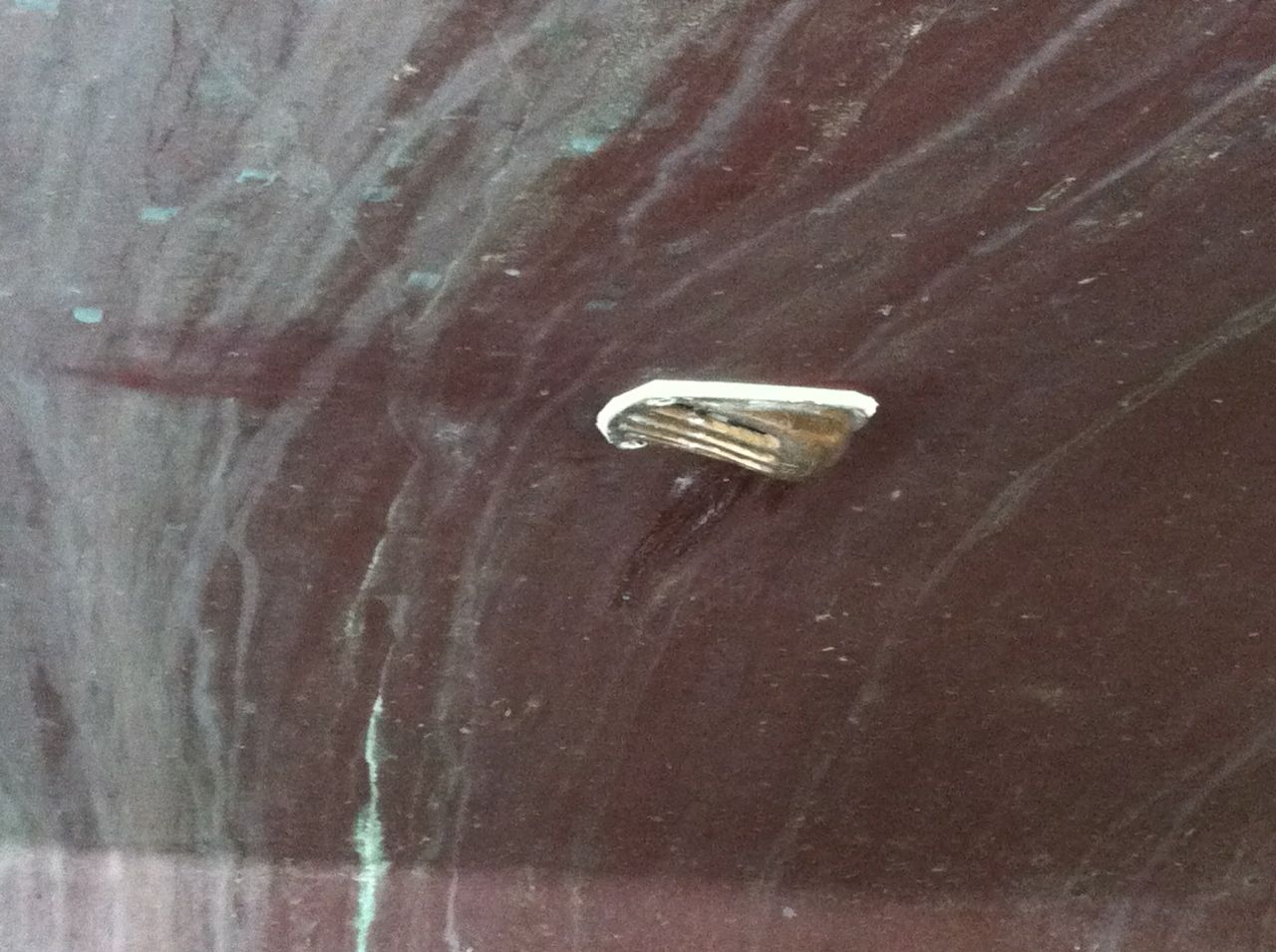
The outside intake is actually a small screen to help keep weeds and such out of the port. |
| |
|
 |
 |
| A close-up of the water intake screen. Using this makes it a little harder to work with because instead of screwing the thru hull into the sea cock, I have to mount this intake then screw the sea cock onto it on the inside. Hopefully when it is tight the sea cock handle will end up in a good spot. |
I used a tube to help keep the plywood backing plate in place as the epoxy dries. Next is to mount the sea cock. |
| |
|
 |
 |
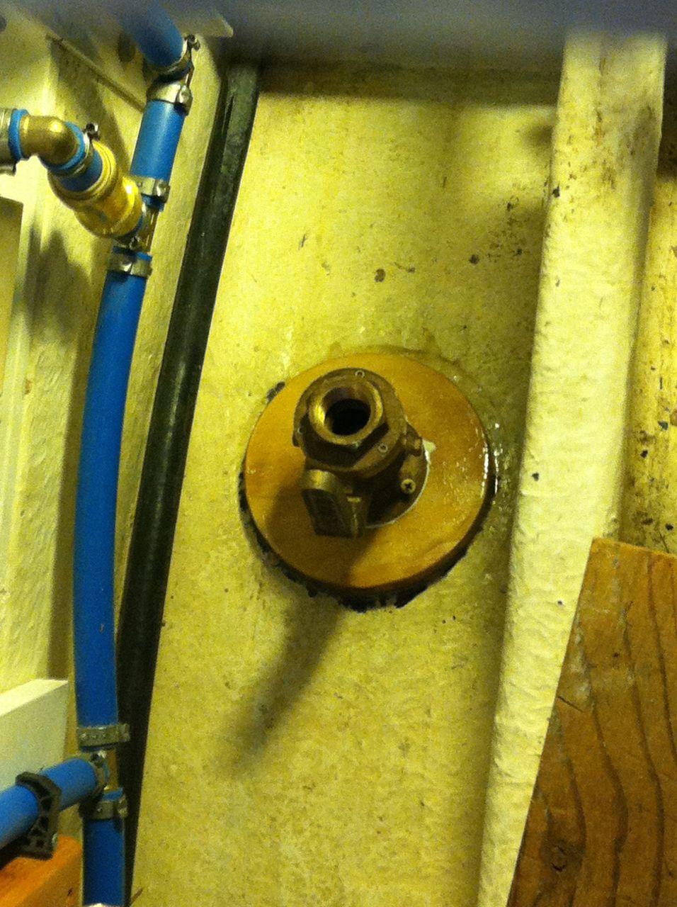
| Sea cock. in place. |
Screen installed on outside of hull. This will keep the seaweed out of the system. |
| |
|
 |
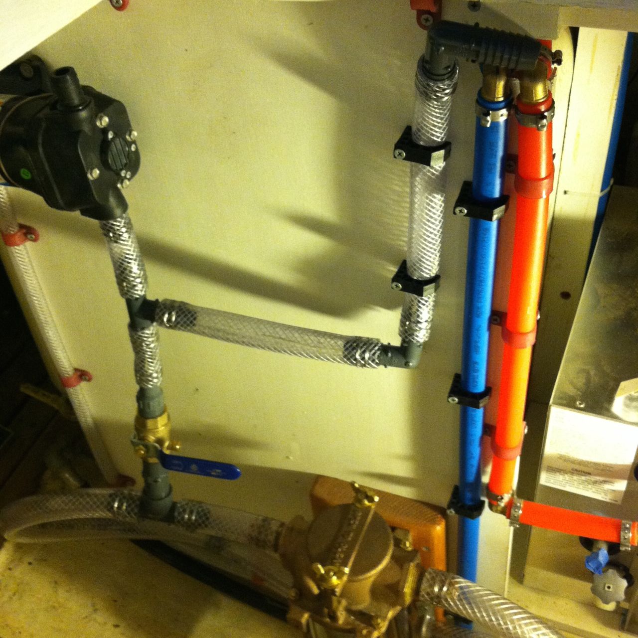 |
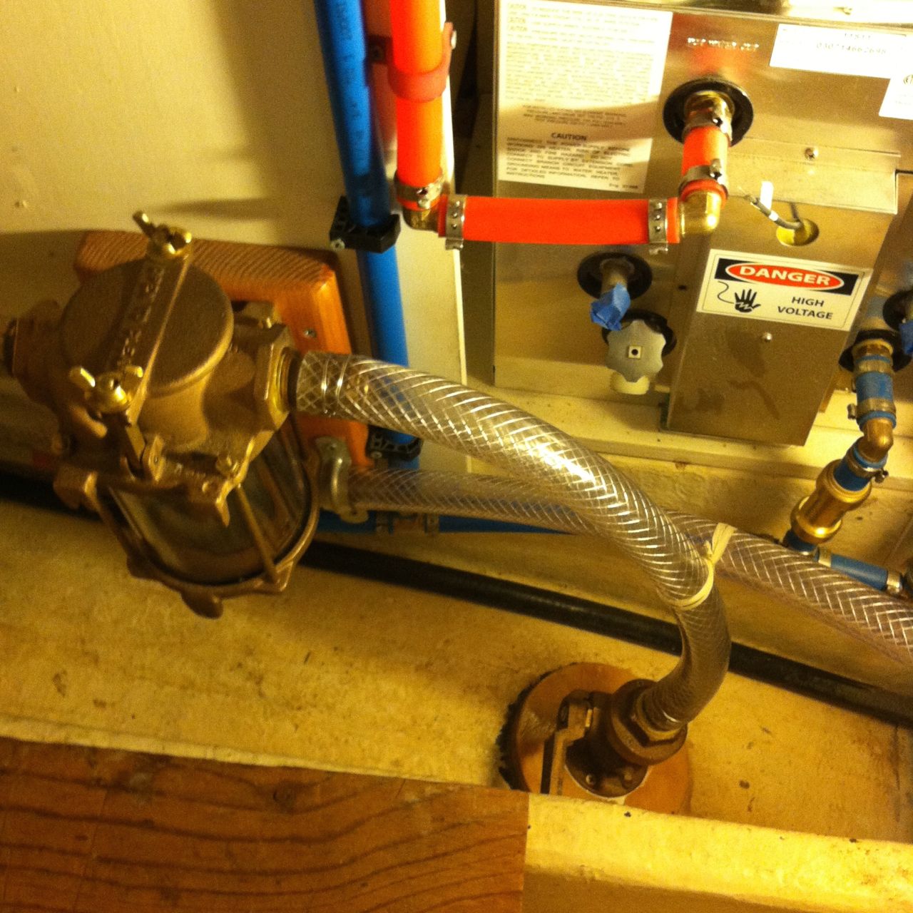
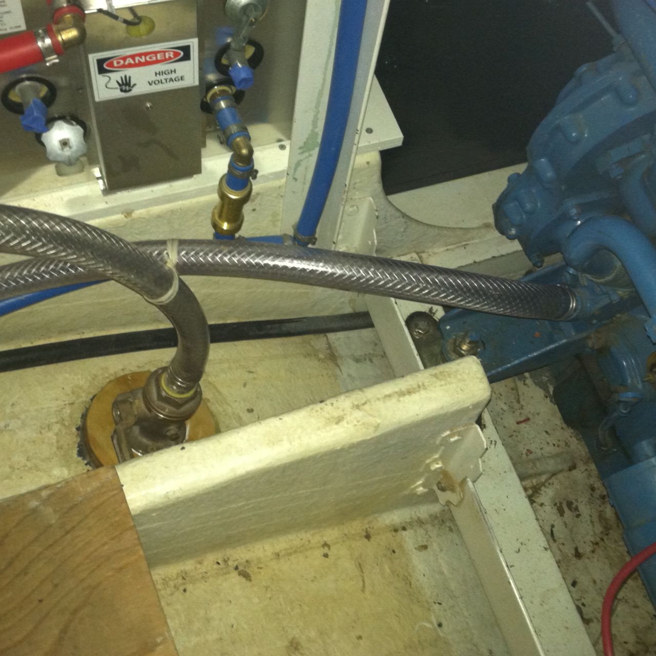
| Sea cock. connected to the strainer. The strainer allows me to clean it out just in case a lot of crap blocks off the water supply. Engine cooling is critical. I am using all clear hose so I can see if there is anything clogging the system. |
From the strainer it goes to the engine on the left, then its T'd to feed the wash down pump and the water maker.
Notice all the stainless wire clamps. I use a clamptite to make clamps where ever I can.
I was going to install the thru-hull on the other side to prevent the loop back to the engine, but the thru-hull needed to be a close to the center of the hull as possible to make sure there's water available when we are healed over. |
| |
|
 |
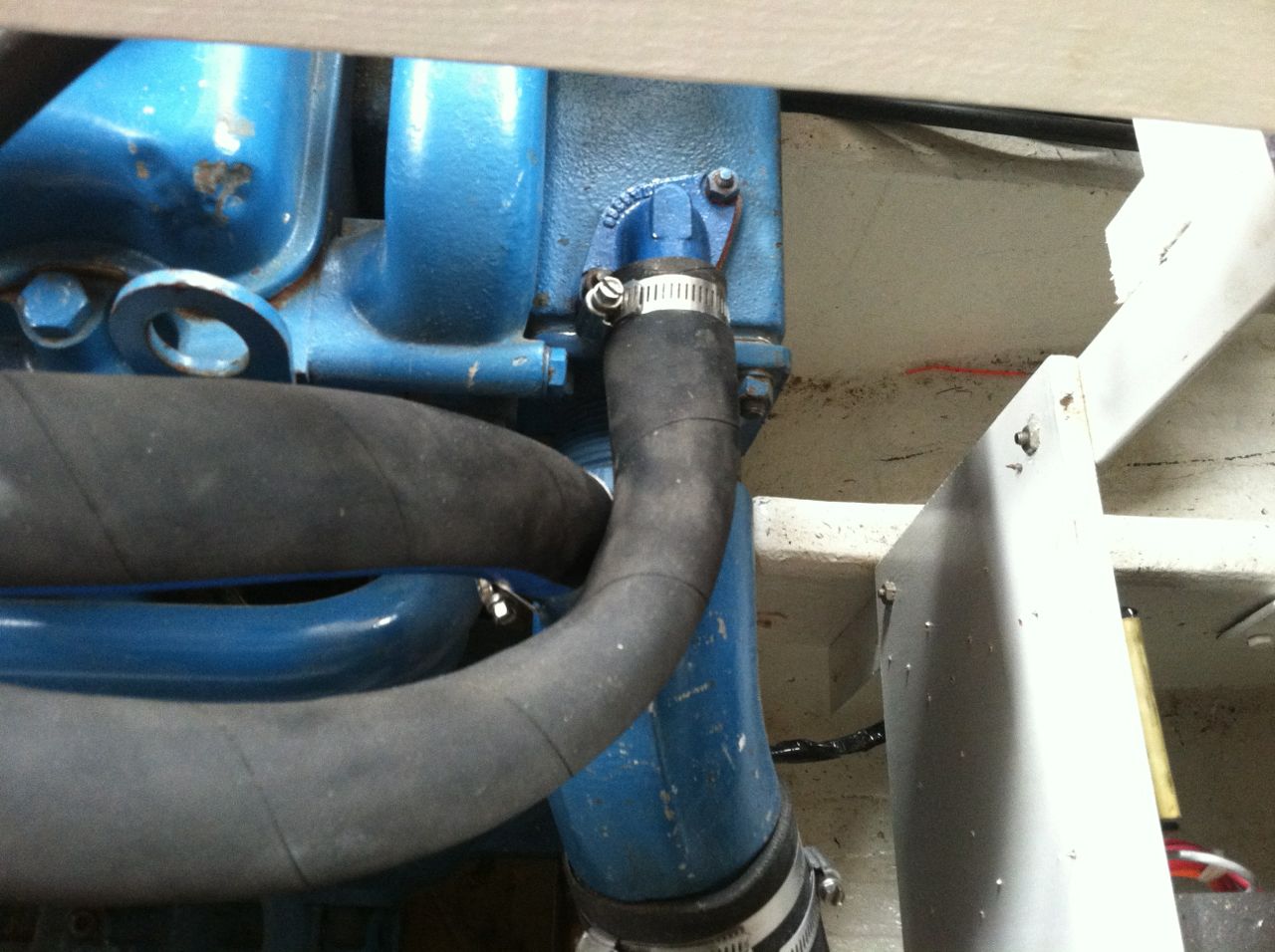 |
| Heres the connection to the engine intake to the pump. |
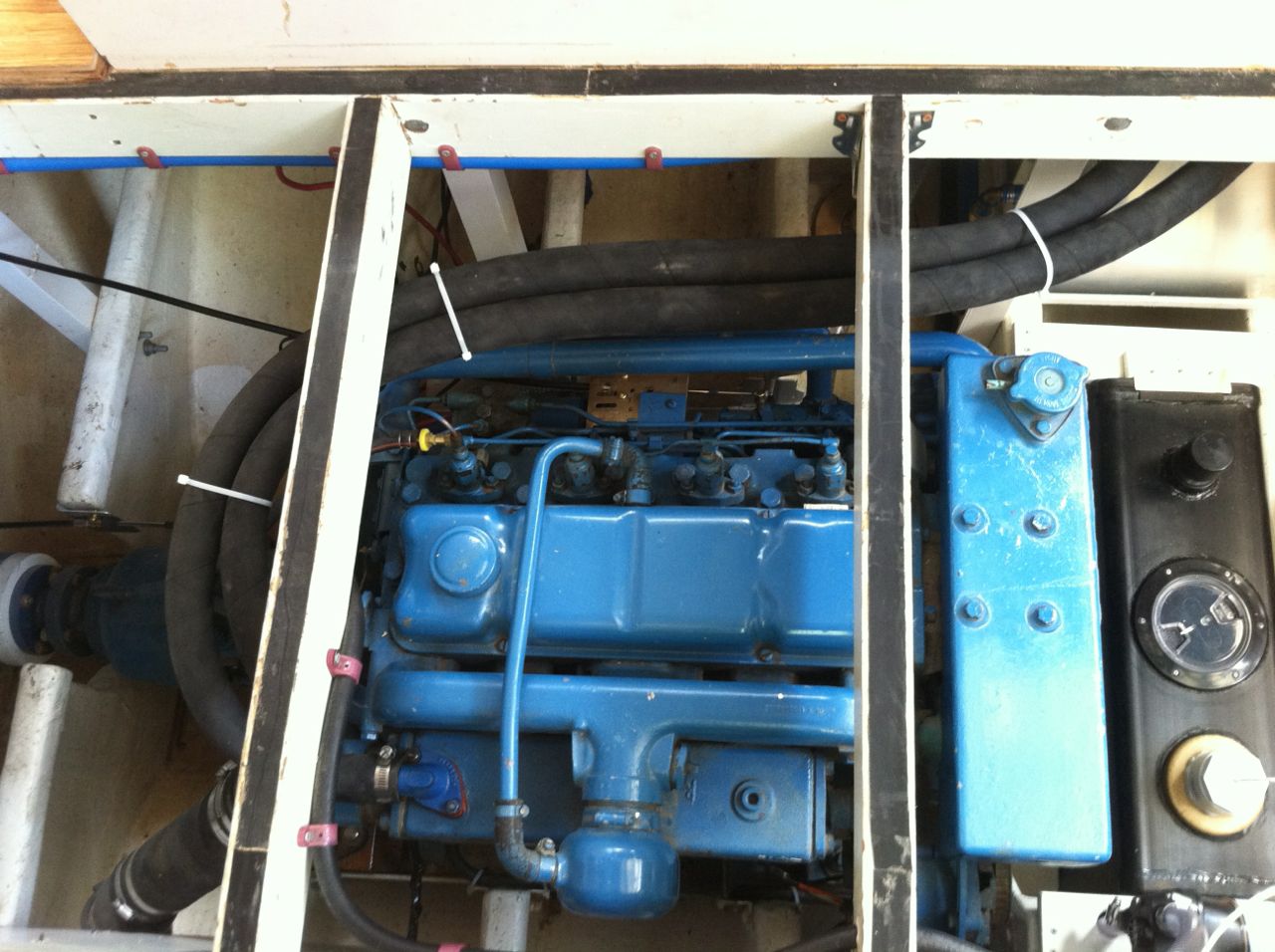
After the salt water cools the engine it comes out hot from the manifold as shown above on the top right. Because it is below the water line we must connect it through a vented loop, which prevents the system from siphoning the salt water and flooding the exhaust system. Then it comes back and enters the exhaust pipe, top left. |
| |
|
 |
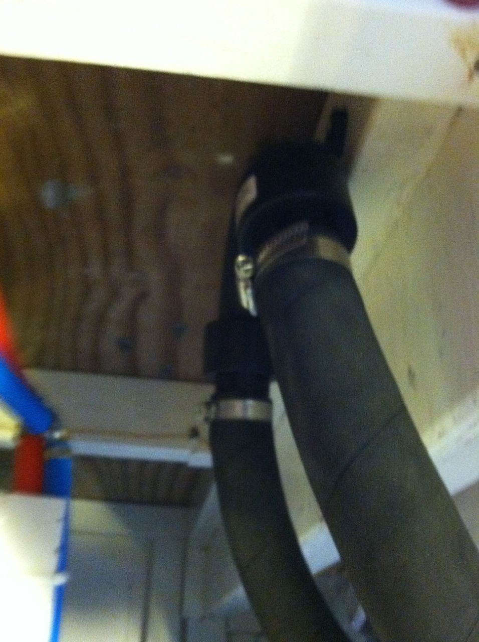 |
| The hoses run forward and up under the settee floor which puts the vented loop about 16 inches above the water line. |
Here's the vented loop. |
| |
|
| Water Heater connection to Engine |
|  |
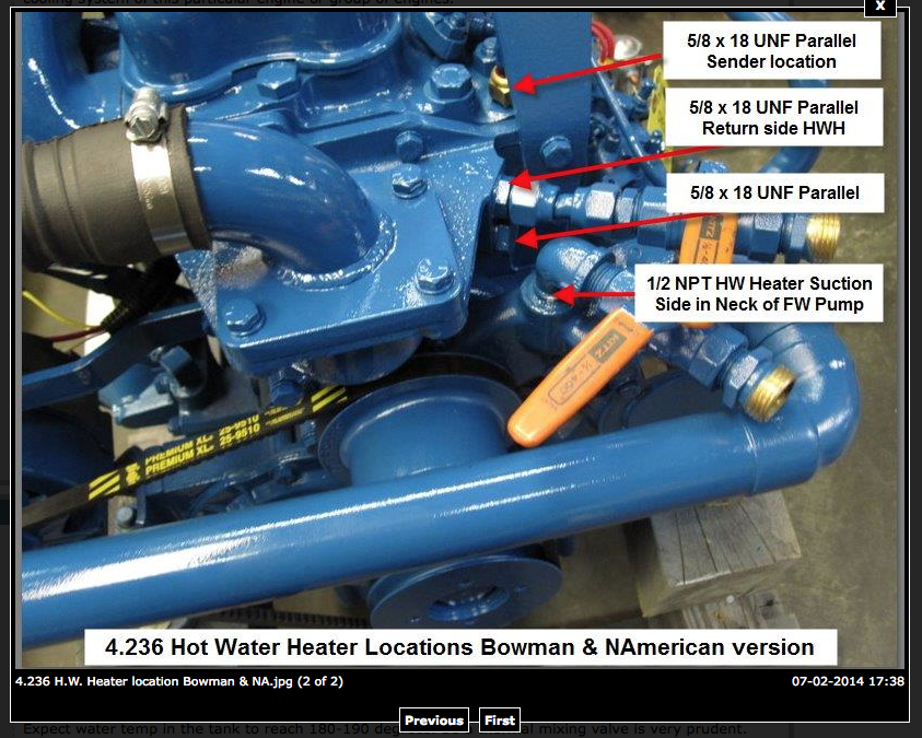
| Here is the lay out I found on the Internet to tap into the pressure and return lines from the cooling system. Another comment was found:
The inlet goes to the water pump discharge right where the big hose comes off and the return goes at the back of the head.
On my engine it is teed with the return on one side and a temp sensor on the other. |
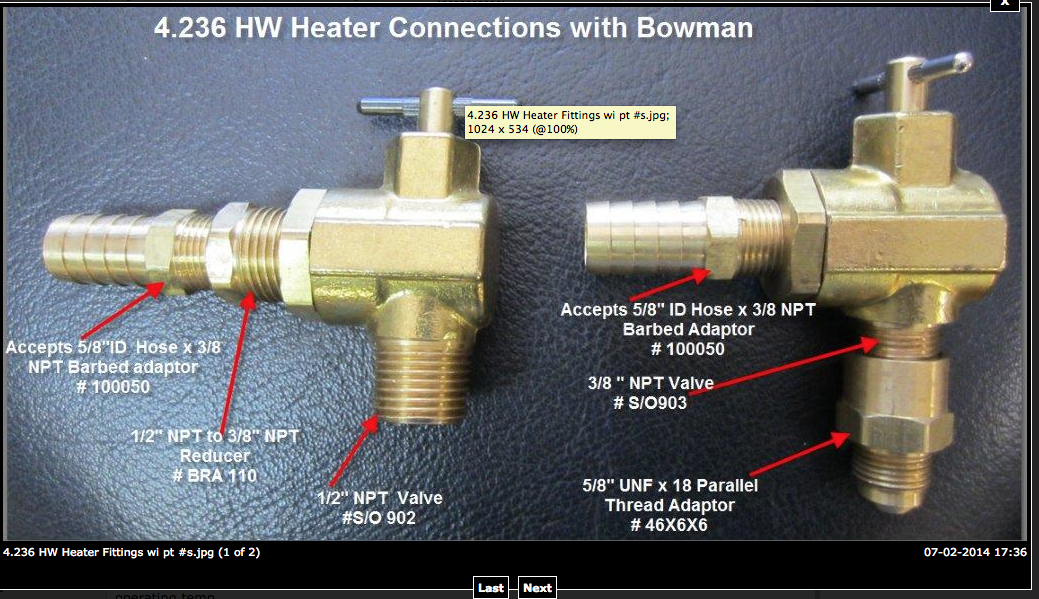
This is the recommended brass fittings needed. All this needs to be double checked. First I need to remove the plugs from the engine and confirm the sizes.
1/2" is supposed to be the suction side, and 5/8 "return side.. Suction and return are the same thing ! |
| |
|